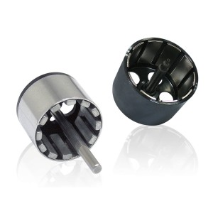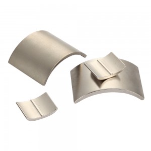

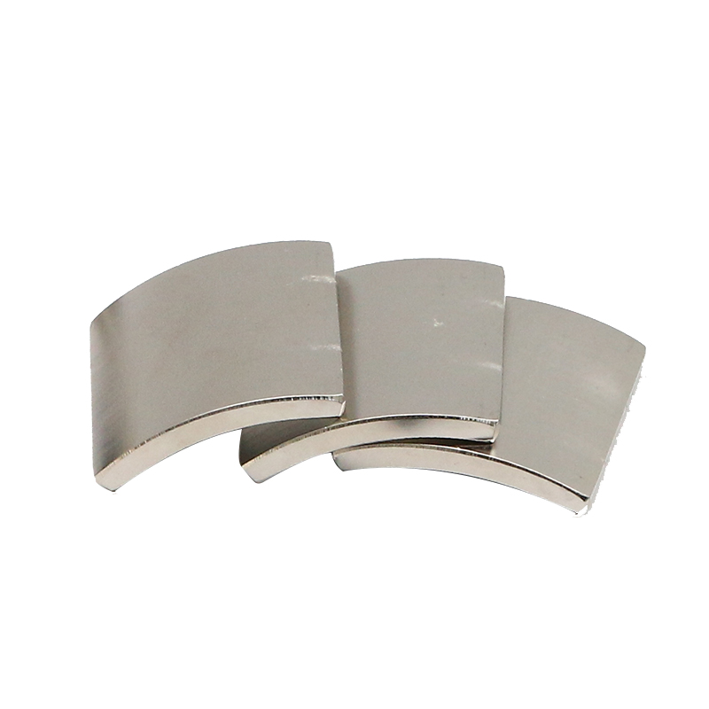

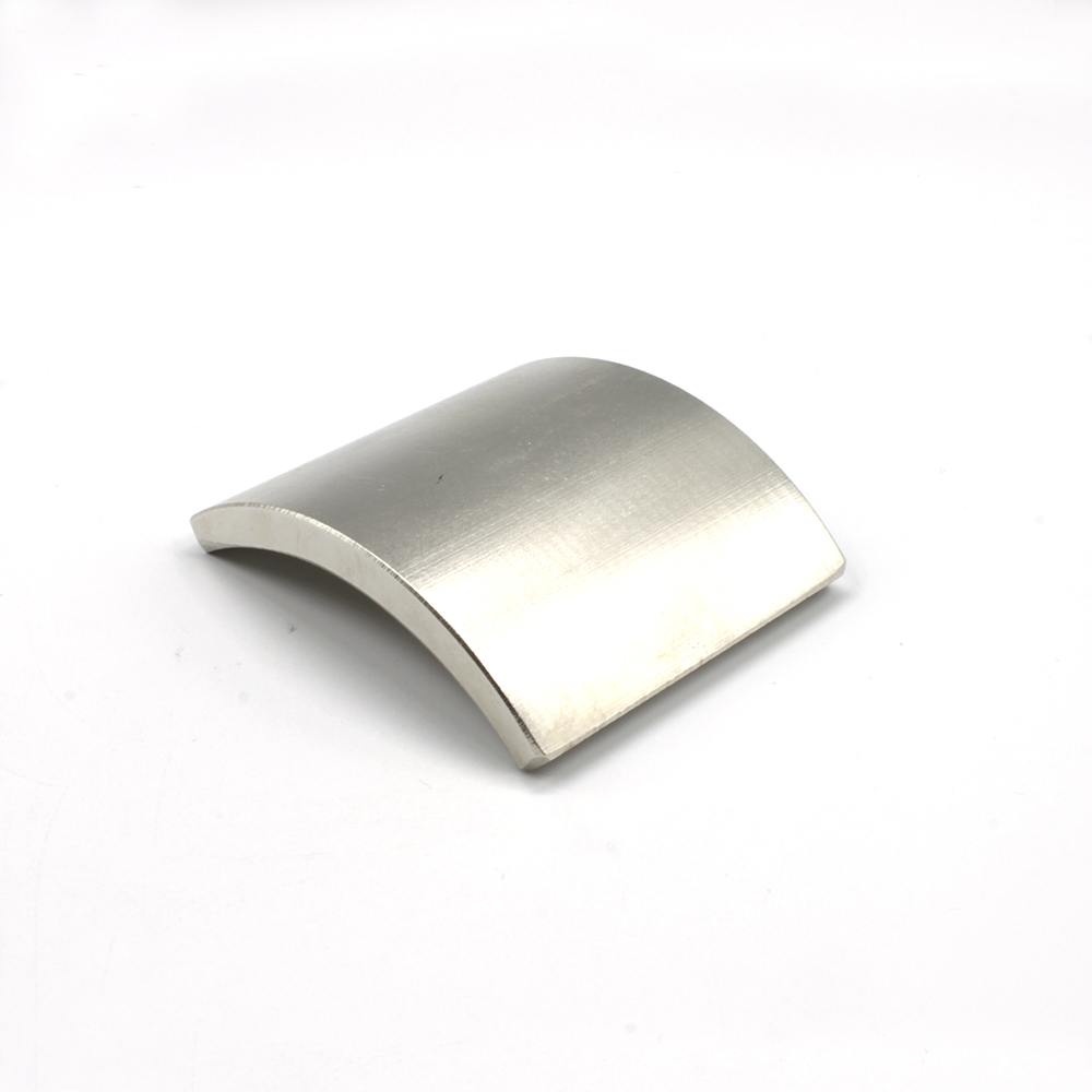
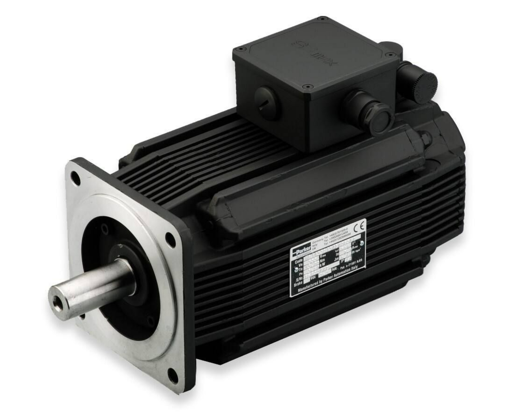
The basic theory of operation for brushless servo motors revolves around the principles of magnetism where like poles repel and opposite poles attract. There are two magnetic sources found within a servo motor: Permanent magnets that are typically located on the rotor of the motor, and the stationary electromagnet that surrounds the rotor. The electromagnet is called either the stator or motor winding and is made up of steel plates called laminations, that are bonded together. The steel plates typically have “teeth” that allow a copper wire to be wound around them.
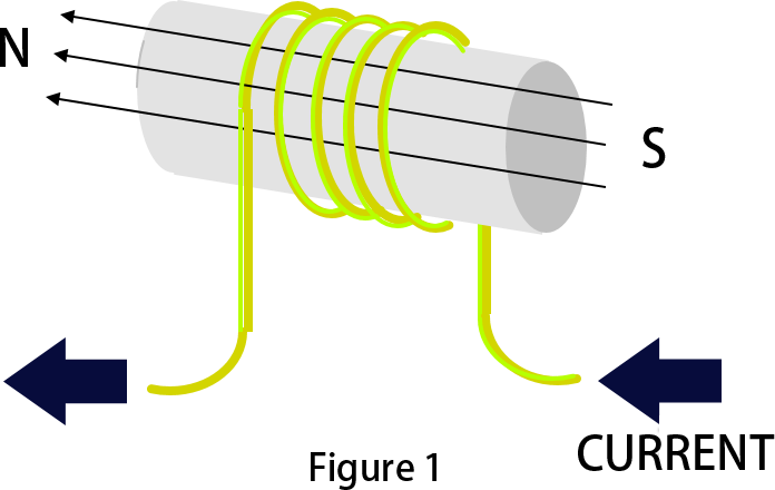
Going back to the principles of magnetism, when a conductor like a copper wire is formed into a coil, and the conductor is energized so that current flows through it, a magnetic field is created.
This magnetic field created by current passing through the conductor will have a north pole and a south pole. With magnetic poles located on the stator (when energized) and on the permanent magnets of the rotor, how do you create a state of opposite poles attracting and like poles repelling?
The key is to reverse the current going through the electromagnet. When current flows through a conducting coil in one direction, north and south poles are created.
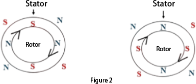
When the direction of the current is changed, the poles are flipped so what was a north pole is now a south pole and vice versa. Figure 1 provides a basic illustration of how this works. In figure 2, the image on the left shows a condition where the poles of the rotor magnets are being attracted to the opposite poles of the stator. The rotor poles, which are attached to the motor shaft, will rotate until they are aligned with the opposite poles of the stator. If all stayed the same the rotor would then remain stationary.
The image on the right in figure 2 shows how the stator poles have flipped. This would happen every time the rotor pole caught up with the opposite stator pole by reversing the current flow through that particular stator location. The continual flipping of stator poles creates a condition where the permanent magnet poles of the rotor are always “chasing” their stator opposites which results in the continuous rotation of the rotor/motor shaft.
The flipping of the stator poles is known as commutation. The formal definition of commutation is “The action of steering currents to the proper motor phases so as to produce optimum motor torque and motor shaft rotation”. How are the currents steered at the correct time to maintain shaft rotation?
The steering is done by the inverter or drive that is powering the motor. When a drive is being used with a particular motor an offset angle is identified in the drive software along with other things like motor inductance, resistance, and other parameters. The feedback device that is used on the motor (encoder, resolver, etc..) provides the position of the rotor shaft/magnetic pole to the drive.
When the magnetic pole position of the rotor matches the offset angle, the drive will reverse the current going through the stator coil thereby changing the stator pole from north to south and from south to north as shown in Figure 2. From this you can see that letting the poles align will stop the motor shaft rotation, or changing the sequence will get the shaft spinning in one direction vs. the other, and changing them quickly allows for a high-speed rotation or just the opposite for slow shaft rotation.